New Developments in Kelly Bar: Key Considerations for Choosing and Maintaining Performance
New Developments in Kelly Bar: Key Considerations for Choosing and Maintaining Performance
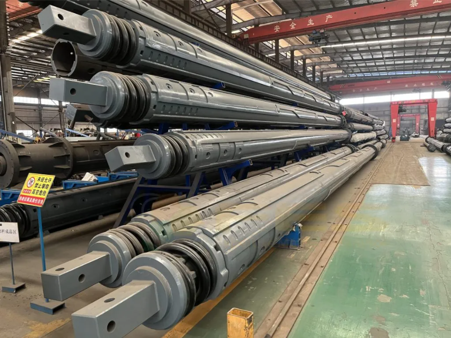
Rotary drilling rods are a critical component in foundation construction, serving as the key link between the drill head and the drill rig’s power unit. They are responsible for transferring torque, drilling pressure, and guiding the direction of drilling operations. The performance of drilling rods directly impacts the drilling depth, adaptability to different soil conditions, and overall construction safety. A high-quality drilling rod, when used properly, can withstand over 100,000 cycles of load. However, improper selection or lack of maintenance can lead to premature failures, causing significant economic losses. This article explores the types, selection principles, and maintenance techniques for rotary drilling rods based on real-world construction scenarios.
Types of Rotary Drilling Rods and Their Suitable Applications
Rotary drilling rods are primarily categorized into two types: friction-type rods and mechanical-lock rods. These two types differ significantly in how they transfer force and their suitability for various soil conditions.
- Friction-Type Drilling Rods
Friction-type rods consist of multiple nested internal and external pipes, with torque and drilling pressure transmitted through friction between the tapered surfaces of the joints. These rods are typically used in 15–36 ton class drilling rigs and are ideal for soft soil and clay layers with low resistance. The main advantages are their flexibility and suitability for construction in areas with low resistance. For example, a 28-ton drilling rig equipped with a friction-type rod was able to complete six piles per day in a silty clay layer (1.2-meter diameter, 35-meter depth), showing significant efficiency. However, friction-type rods have limitations when working in hard layers, especially when drilling pressure exceeds 150kN, which may cause slippage, reducing transmission efficiency to below 70%. - Mechanical-Lock Drilling Rods
Mechanical-lock rods use a key-and-lock mechanism to transmit force and can withstand high drilling pressures of 300–600 kN, making them the preferred choice for tough soil conditions such as hard rock or gravel layers. A 45-ton drilling rig equipped with six mechanical-lock rods successfully drilled through a 50-meter-thick moderately weathered rock layer during a hydroelectric project. The rod’s service life reached 800 hours, twice as long as that of the friction-type rods. Additionally, there are specialized rods designed for unique working conditions, such as casing rods used together with FES piling casing to prevent hole collapse, and telescopic rods for tight space operations. In a metro station construction project, a telescopic mechanical-lock rod was used to drill a 1.5-meter diameter, 40-meter-deep foundation pile in an 8-meter-wide work area, addressing the limitations of conventional rods.
Key Parameters for Selecting Rotary Drilling Rods
The selection of the right rotary drilling rod involves matching the following three key factors: drill rig tonnage, soil hardness, and desired drilling depth. The core parameters to consider are rated torque, maximum drilling pressure, and the number of rod sections.
- Rated Torque
The rated torque should be 10–15% lower than the output torque of the drill rig’s power head, providing a safety buffer. For example, a 360kN·m power head should be paired with a rod rated for 300–320kN·m to avoid overloading. A construction site experienced a failure when using a rod with insufficient torque capacity, resulting in rod twisting and deformation during drilling in gravel layers, costing over 100,000 yuan in repairs. - Maximum Drilling Pressure
The maximum drilling pressure should be determined based on the soil’s uniaxial compressive strength (Rc). For soft soil (Rc < 20MPa), drilling pressures of 150–200kN are sufficient. For medium-hard soils (20 ≤ Rc ≤ 50MPa), 250–350kN is required, while hard rock layers (Rc > 50MPa) demand drilling pressures above 400kN. For example, during construction in granite soil (Rc = 80MPa), a 500kN mechanical-lock rod was paired with 350kN drilling pressure to achieve a drilling speed of 1.2 meters per hour, compared to just 0.3 meters per hour with a 300kN rod. - Number of Sections
The number of sections determines the drilling depth. Standard rods are 6–9 meters in length, and too many sections can reduce overall rigidity. The selection principle follows a “just enough” rule: for depths of 30 meters, choose 3–4 sections; for depths up to 50 meters, choose 5–6 sections; for depths over 80 meters, 7–8 sections are required. For deeper foundations, a guiding frame is recommended for increased stability.
Common Problems with Drilling Rods and Preventative Measures
- Rod Breakage
Rod breakage often occurs at high-stress points, such as the joints and lock grooves, accounting for over 70% of failures. Regular cleaning of the joints to remove dirt and drilling residue can help prevent premature wear. It’s crucial to inspect welds weekly and repair any cracks (even as small as 0.5mm) using low-hydrogen welding rods. Additionally, controlling “shock loading” during drilling can prevent overloading and rod breakage. For example, installing a torque sensor helped reduce breakage incidents from 2 per month to 0.5 in a mining project. - Wear of Lock Blocks
In mechanical-lock rods, lock blocks are the most vulnerable parts. In hard soils, the wear rate can reach 1–2mm per 100 meters drilled. When wear exceeds 3mm, it can lead to difficulty in locking or loss of force transmission. Routine maintenance involves checking the gap between the lock block and key slot (should be ≤ 0.5mm). If the gap exceeds this value, the lock block should be replaced. Special lubricants designed for high temperatures should be used to ensure proper functioning. - Bending Deformation
Rod bending usually results from improper storage or uneven force during drilling. When bending exceeds 1‰ (more than 1mm deviation per meter), it can cause drilling vibrations and accelerate wear on other components. To detect this, the “string method” can be used to measure bending. If bending exceeds the standard, the rod should be straightened using thermal methods (heating to 600–650°C). Cold bending is not recommended, as it can cause permanent cracks in the rod.
Maintenance System for Rotary Drilling Rods
Establishing a “three-tier maintenance” system is crucial for extending the service life of drilling rods used with FES foundation drilling tools. Daily maintenance includes cleaning the joints, inspecting welds, lubricating the rods, and checking smooth movement. Regular maintenance every 50 hours involves measuring wear on lock blocks, inspecting seals, and testing joint gaps. Seasonal maintenance every 6 months focuses on corrosion prevention, including sandblasting to remove rust and applying a coat of epoxy primer and wear-resistant paint.
Long-term storage should be done horizontally on specialized racks, with a height of at least 30cm off the ground, avoiding direct sunlight and rain. Multi-section rods should be stored separately to prevent bending from self-weight. A rental company, for example, managed to limit the rust rate of rods stored for 6 months to 5%, far below the industry average of 20%.
The selection and maintenance of rotary drilling rods require careful attention to detail. By ensuring the rods are well-matched to specific project requirements and following a regimented maintenance schedule, contractors can maximize efficiency and minimize downtime, ensuring a safe and cost-effective drilling process.


Comments
Post a Comment